The board has two main components:
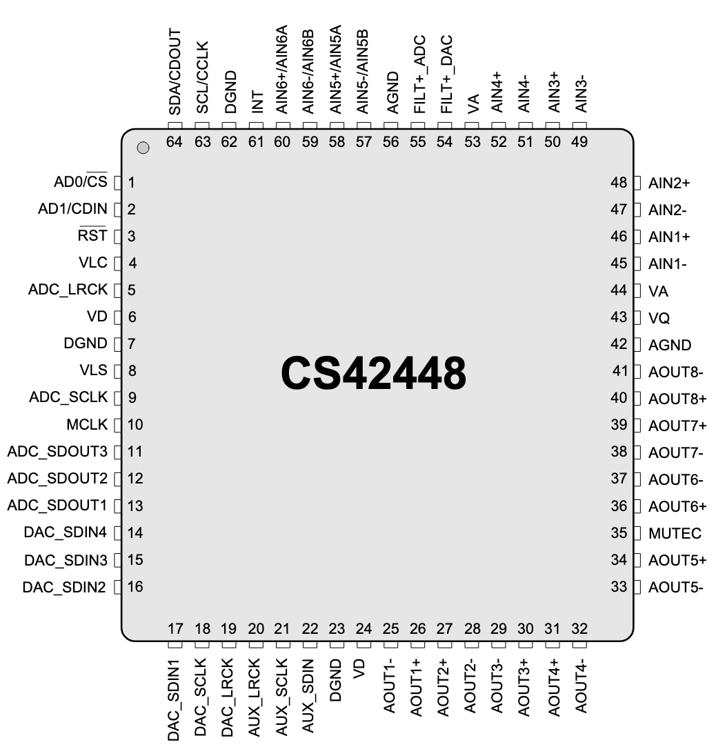
- Two Cirrus Logic CS42448 6-in 8-out codecs
- One ADAU1466 SigmaDSP Compact Digital Audio Processor with Extended Internal Memory
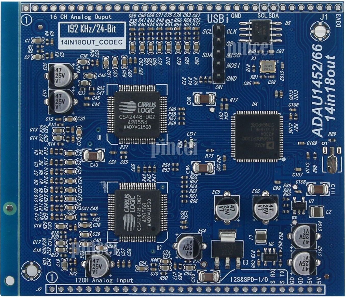
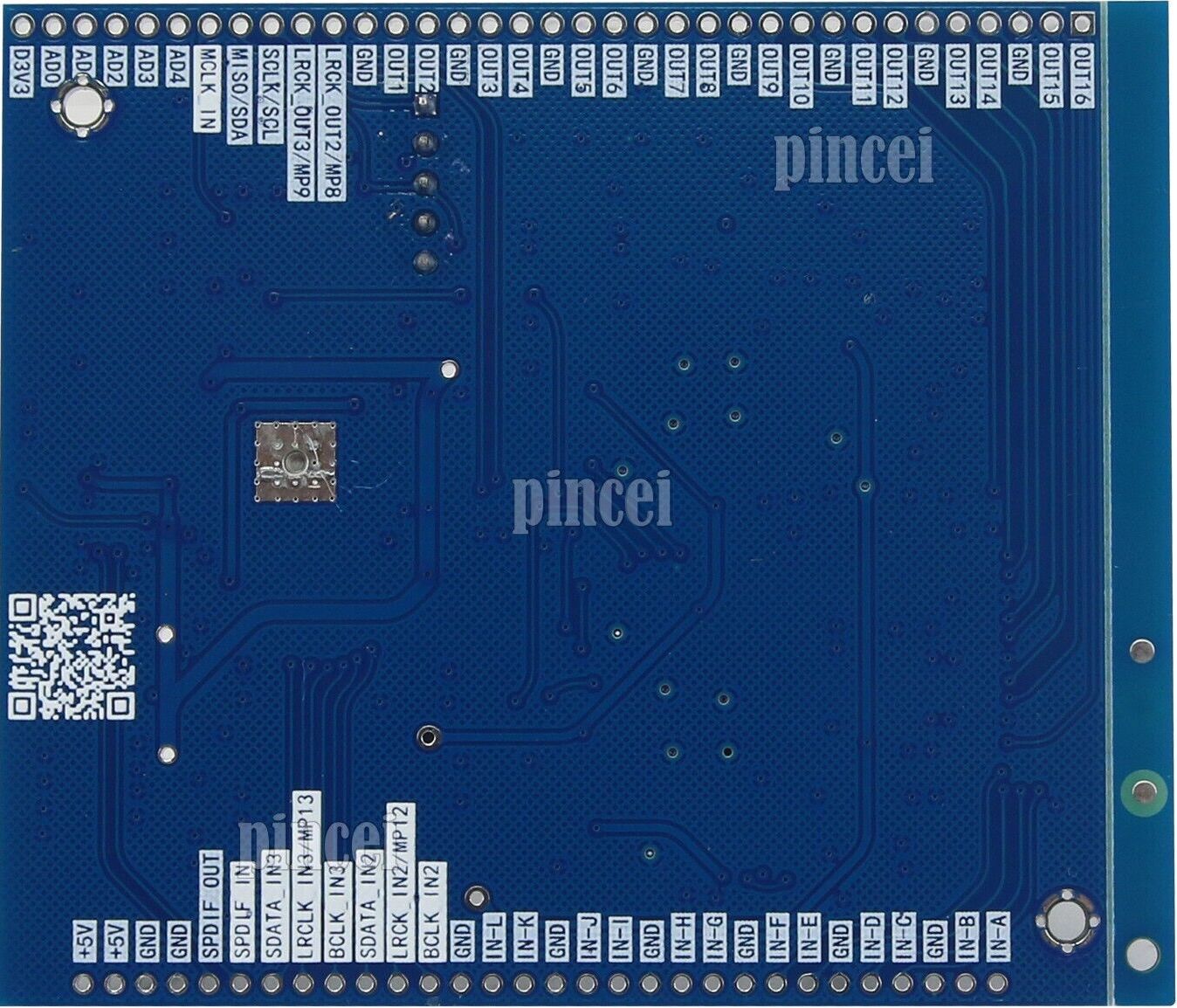
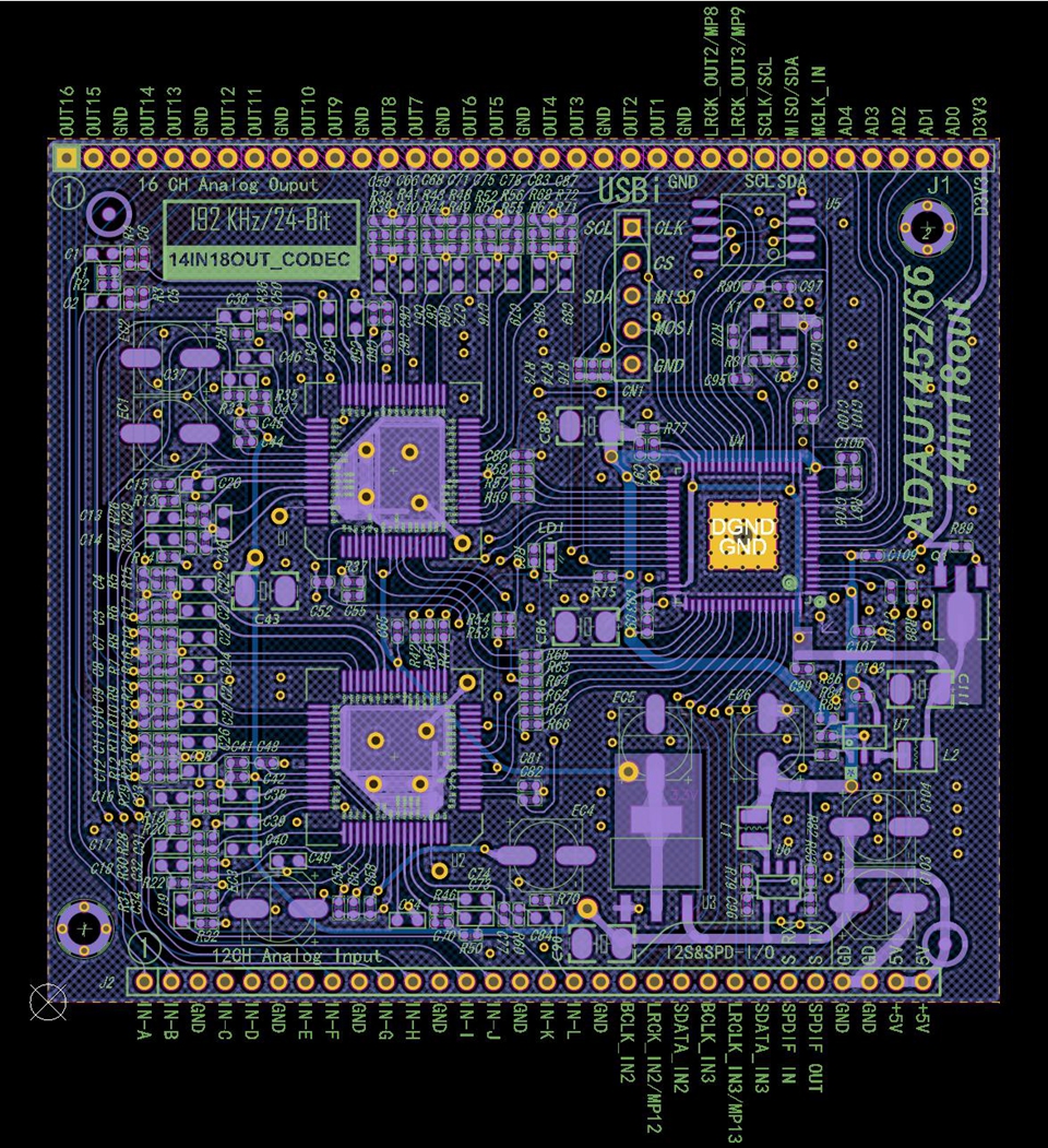
The PCB traces reveal that the I2C pins of both Codecs are not connected – this means the chips can not be actively configured and operate in standalone, i.e., TDM-8 mode.
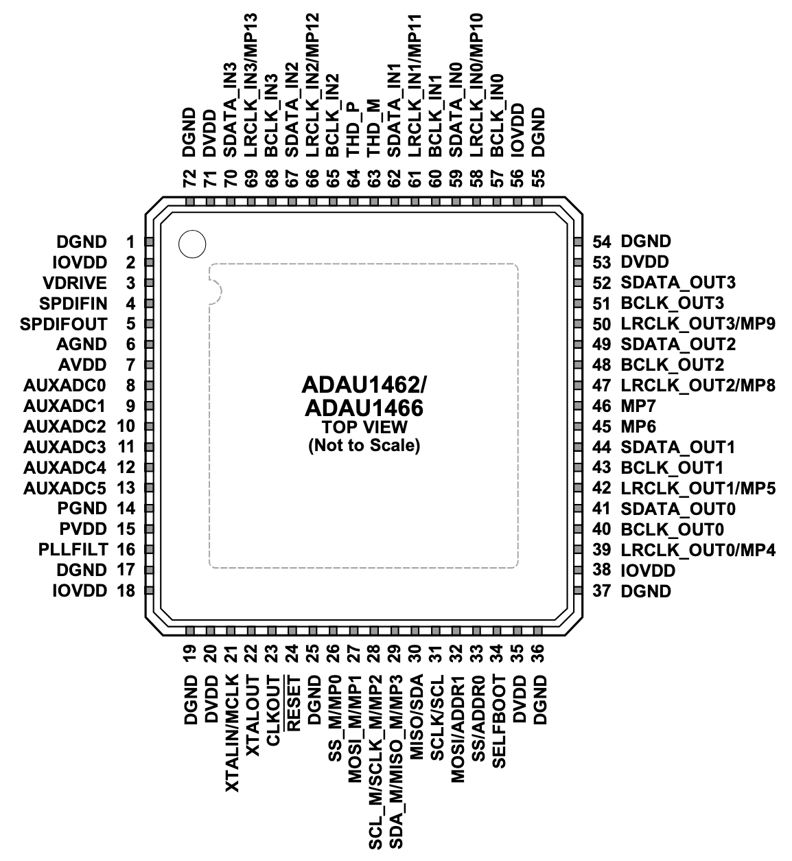
The pinouts of the chips are as following:
Some experiences with this and similar boards have amassed in a long forum thread on diyAudio.
Programming
Tutorial: How to program an Analog Devices DSP
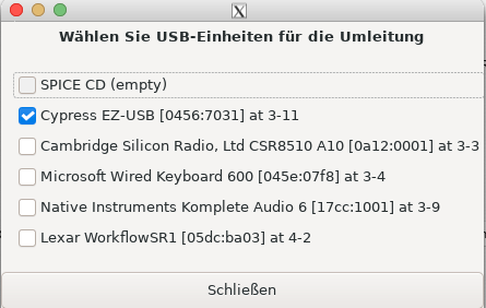
This uses an FX2LP-CY7C68013A-based logic analyzer board, also known as "Cypress EZ-USB".
By lsusb, it is reported as
Bus 003 Device 011: ID 0456:7031 Analog Devices, Inc. FX2 SPI/I2C Interface
For programming the DSP, AD's SigmaStudio software is used, running under Windows.
Running AD SigmaStudio under Linux
Using a virtual machine, e.g. virt-manage it is possible to install Windows under linux.
For this, the running user needs to be in the kvm group:
sudo adduser $USER kvm
There are several caveats:
There can be collisions with running dnsmasq services which use port 53. libvirtd wants to use the same port. The solution is to restrict dnsmasq to certain interfaces on the host system with settings in /etc/dnsmasq.conf:
bind-interfaces
interface=enp8s0  # the interface to use for dnsmasq
Restart with sudo service dnsmasq restart.
Also, SigmaStudio should be able to communicate with USB devices. This must be enabled in several ways
First, create a group spice and assign the user running virt-manage to it:
sudo groupadd spice
sudo adduser $USER spice
Create /etc/udev/rules.d/50-spice.rules with the following content:
SUBSYSTEM=="usb", GROUP="spice", MODE="0660"
SUBSYSTEM=="usb_device", GROUP="spice", MODE="0660"
Add <allow_any>yes</allow_any> to /usr/share/polkit-1/actions/org.spice-space.lowlevelusbaccess.policy which then looks like:
<?xml version="1.0" encoding="UTF-8"?>
<!DOCTYPE policyconfig PUBLIC
          "-//freedesktop//DTD PolicyKit Policy Configuration 1.0//EN"
          "http://www.freedesktop.org/standards/PolicyKit/1.0/policyconfig.dtd">
<policyconfig>

  <vendor>The Spice Project</vendor>
  <vendor_url>http://spice-space.org/</vendor_url>
  <icon_name>spice</icon_name>

  <action id="org.spice-space.lowlevelusbaccess">
    <description>Low level USB device access</description>
    <message>Privileges are required for low level USB device access (for usb device pass through).</message>
    <defaults>
      <allow_any>yes</allow_any>
      <allow_inactive>no</allow_inactive>
      <allow_active>yes</allow_active>
    </defaults>
  </action>

</policyconfig>
The virtual machine manager is started with virtual-manager.
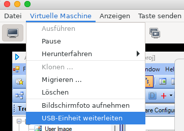
For the virtual machine, the USB device must be forwarded anew at every session.
Programming the DSP in SigmaStudio
In SigmaStudio, we drag in "USBi" and "ADAU1466" devices. If the connection to the Cypress dongle works, the USB device has a green header.
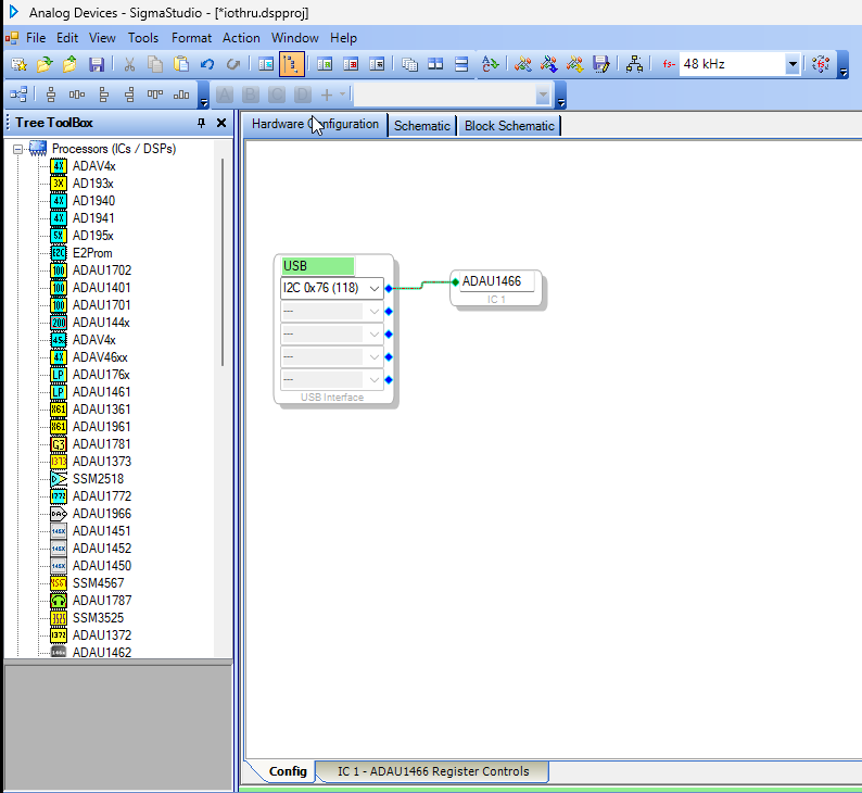
This does not mean that the connection to the DSP board works. Specifically, we have to find out whether the SPI or I2C protocols are used, and which address.
We can do this using a little test program using a DC generator (Sources / DC / DC Input Entry) and a Readback cell (Basic DSP / DSP Functions / DSP Readback):
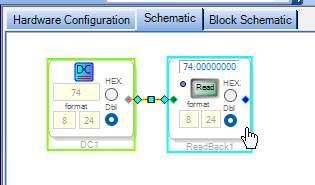
We "Link Compile Download" the schematic using the respective toolbar button or the menu item in the Action menu (or keyboard shortcut F7). If the upload succeeded we can set the DC to some value and read back the value in the Readback object pushing the Read button. It must match the set DC value.
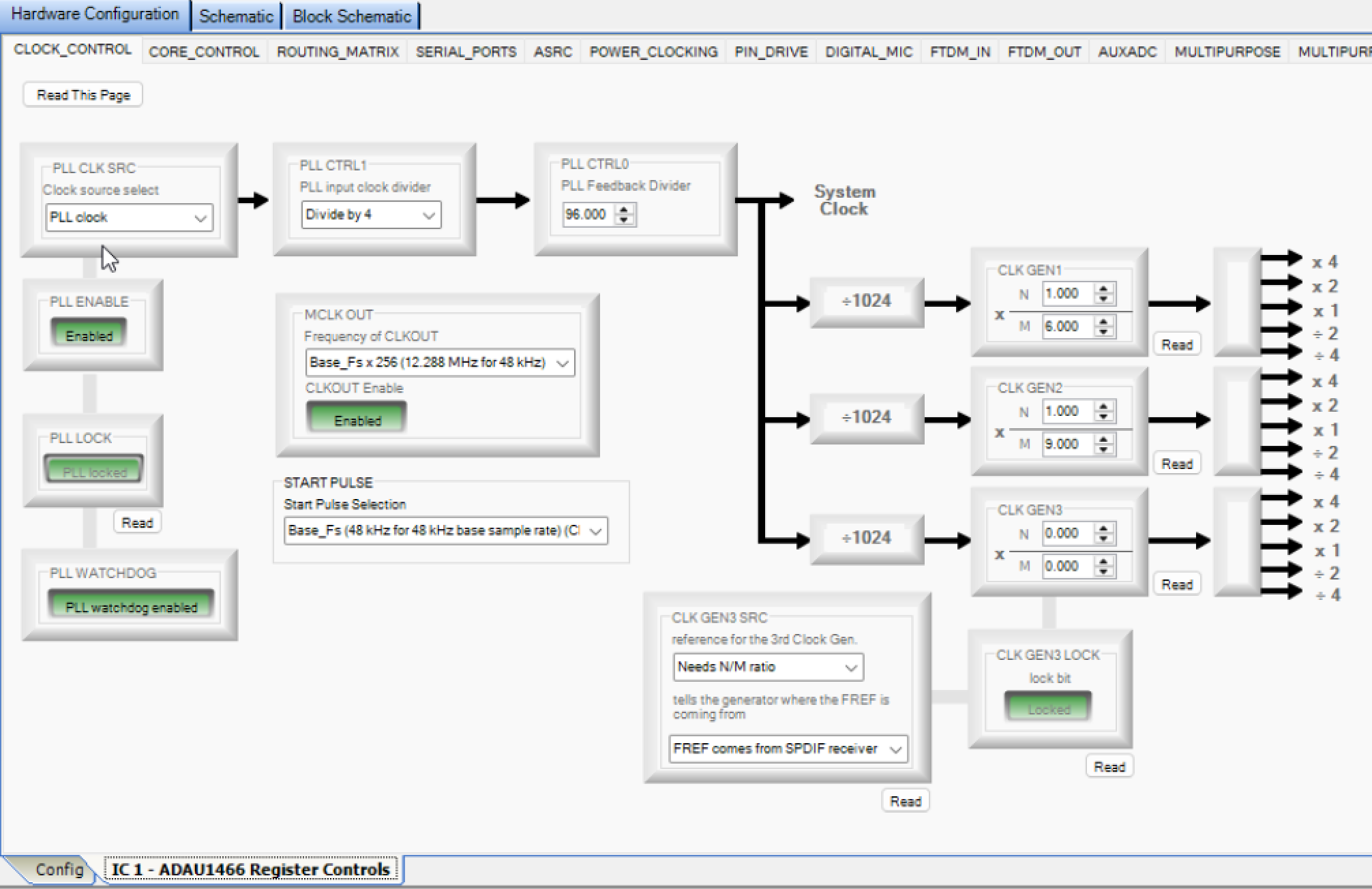
Hardware configuration of the board
The hardware configuration should look like the following. Specifically, in our configuration, the PLL CLK SRC should be internal (PLL clock) and the MCLK OUT must be Base_Fs x 256.
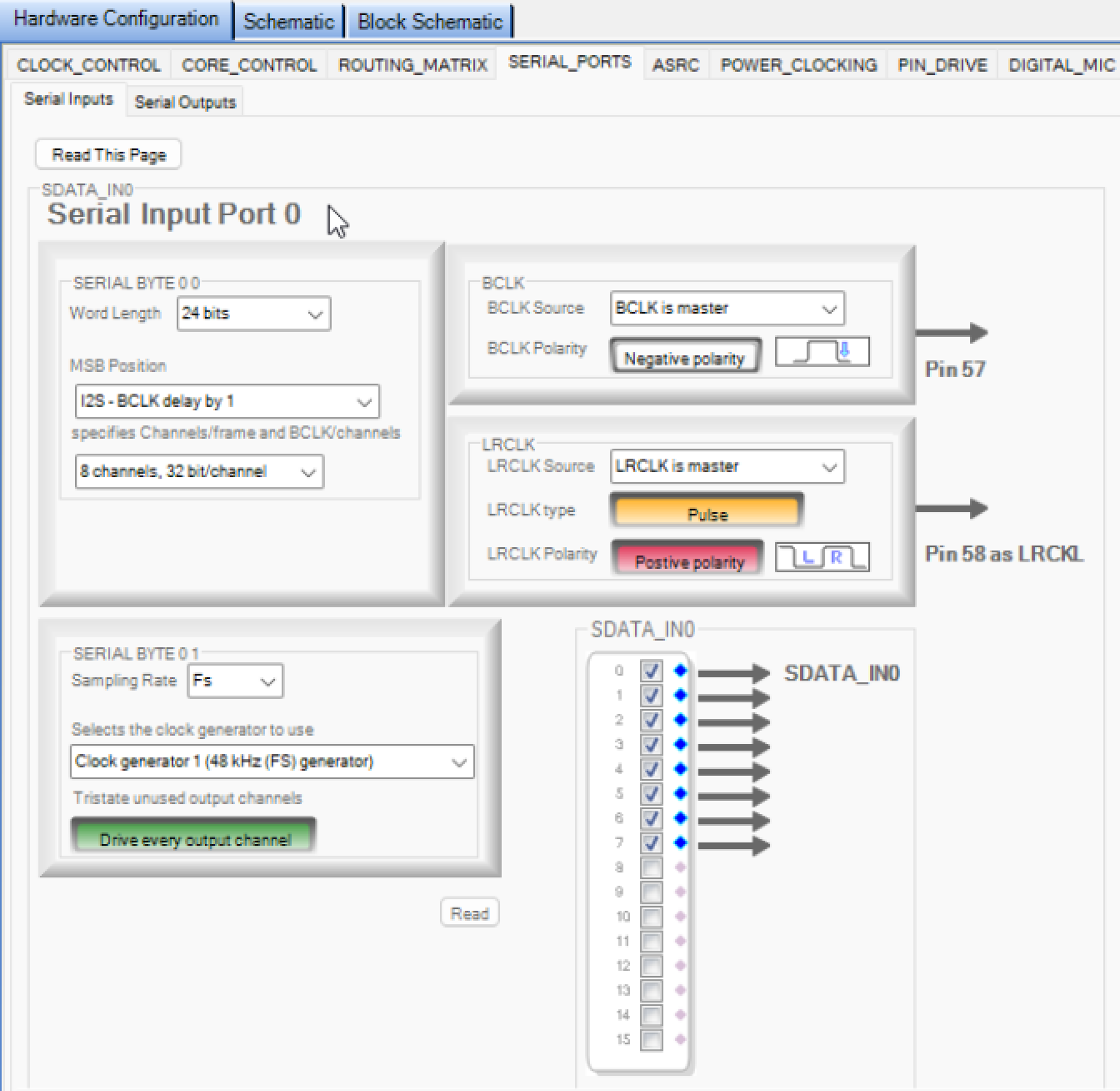
In order for the two DSP chips to work in standalone mode, the serial interface settings must be set like in the following screen shot. This applies to both input and output serial ports 0 and 1.
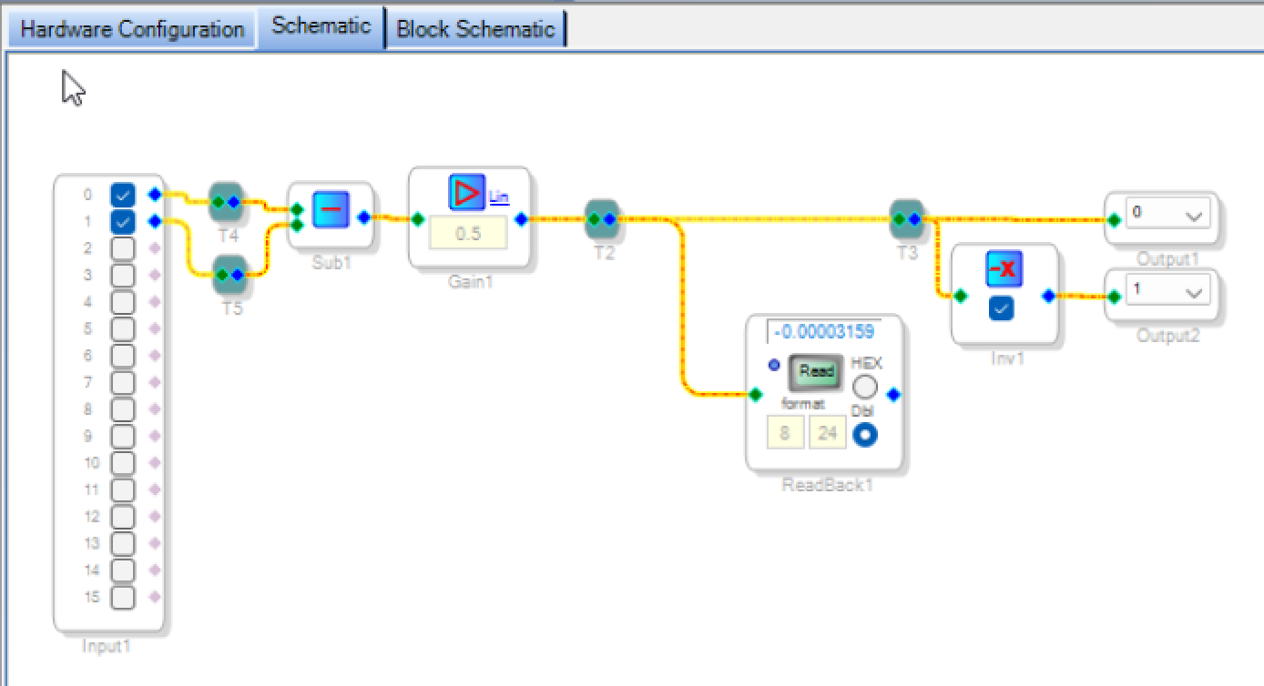
A very simple audio through patch receiving symmetric audio (through audio inputs 0 and 1) and sending symmetric audio (through audio outputs 0 and 1) can look like the following. On Read of the Readback object, different numbers should be displayed.
Input/output test
THD and THD+N
We would like to find out which input and output volume is ideal in terms of THD and THD+N.
For this, we have an audio file of a high-quality 100 Hz sine wave (generated in Python) which we run from a linux computer through a RME UCX-II audio card in class-compliant (CC) mode. The file is in S32LE format at 48 kHz sample rate and -6 dB RMS (±0.5 peak amplitude). We use the device outputs/inputs 1 and 2, the output gain is set to 0 dB, the input gain to 10 dB.
The audio device needs the S24LE format. With the -filter:a "volume=… option, we set the playback volume of the file.
ffmpeg -stream_loop -1 -i ~/Musik/sine100-6db-48k-int32.wav -f alsa -filter:a "volume=+0dB" -c:a pcm_s24le plughw:CARD=II24240477
Channel 1 is routed through the DSP to input 1, while channel 2 is routed directly to the input 2 using a TRS cable, for reference. Both inputs and outputs of the audio device are balanced.
We start with a test of the input stage. For this, we set the factor in the Gain1 object to 0.1 to never saturate the output.
volume=+6dB: THD ref: 0.00093%, THD rec: 3.28017% / THD+N ref: 0.00102%, THD+N rec: 3.27844%
volume=+3dB: THD ref: 0.00068%, THD rec: 0.05737% / THD+N ref: 0.00088%, THD+N rec: 0.05846%
volume=+0dB: THD ref: 0.00053%, THD rec: 0.02055% / THD+N ref: 0.00096%, THD+N rec: 0.02633%
volume=-3dB: THD ref: 0.00047%, THD rec: 0.02485% / THD+N ref: 0.00122%, THD+N rec: 0.03507%
volume=-6dB: THD ref: 0.00050%, THD rec: 0.01715% / THD+N ref: 0.00164%, THD+N rec: 0.04140%
Obviously, the +6 dB setting clips the input signal.
Now, we set the gain stage back to 0.5:
volume=+3dB: THD ref: 0.00067%, THD rec: 0.05610% / THD+N ref: 0.00089%, THD+N rec: 0.05613%
volume=+0dB: THD ref: 0.00055%, THD rec: 0.05069% / THD+N ref: 0.00097%, THD+N rec: 0.05073%
volume=-3dB: THD ref: 0.00048%, THD rec: 0.04455% / THD+N ref: 0.00120%, THD+N rec: 0.04469%
volume=-6dB: THD ref: 0.00051%, THD rec: 0.03936% / THD+N ref: 0.00169%, THD+N rec: 0.03978%
A comparison with unbalanced input at the DSP:
volume=+0dB: THD rec: 0.08419% / THD+N rec: 0.08627%
We fix to volume=+0dB, which seems to be a good setting, now trying different Gain1settings:
Gain1=-12dB: THD rec: 0.03414% / THD+N rec: 0.03433%
Gain1=-15dB: THD rec: 0.03962% / THD+N rec: 0.04051%
Gain1=-18dB: THD rec: 0.02094% / THD+N rec: 0.02491%
Gain1=-21dB: THD rec: 0.01460% / THD+N rec: 0.02310%
Gain1=-24dB: THD rec: 0.00910% / THD+N rec: 0.02831%
Gain1=-27dB: THD rec: 0.00722% / THD+N rec: 0.04305%
The setting around -21 dB for Gain1 seems ideal.
The following graphs show measurements of this signal through the DSP (label rec) and through the direct reference channel (label ref). At every point, the reference levels are considerably lower than the investigated signal, also the f1 peak at 200 Hz.
For the DSP, the by far loudest distortion artifact is at f2 (300 Hz), ca. -75 dB below the excitation signal.
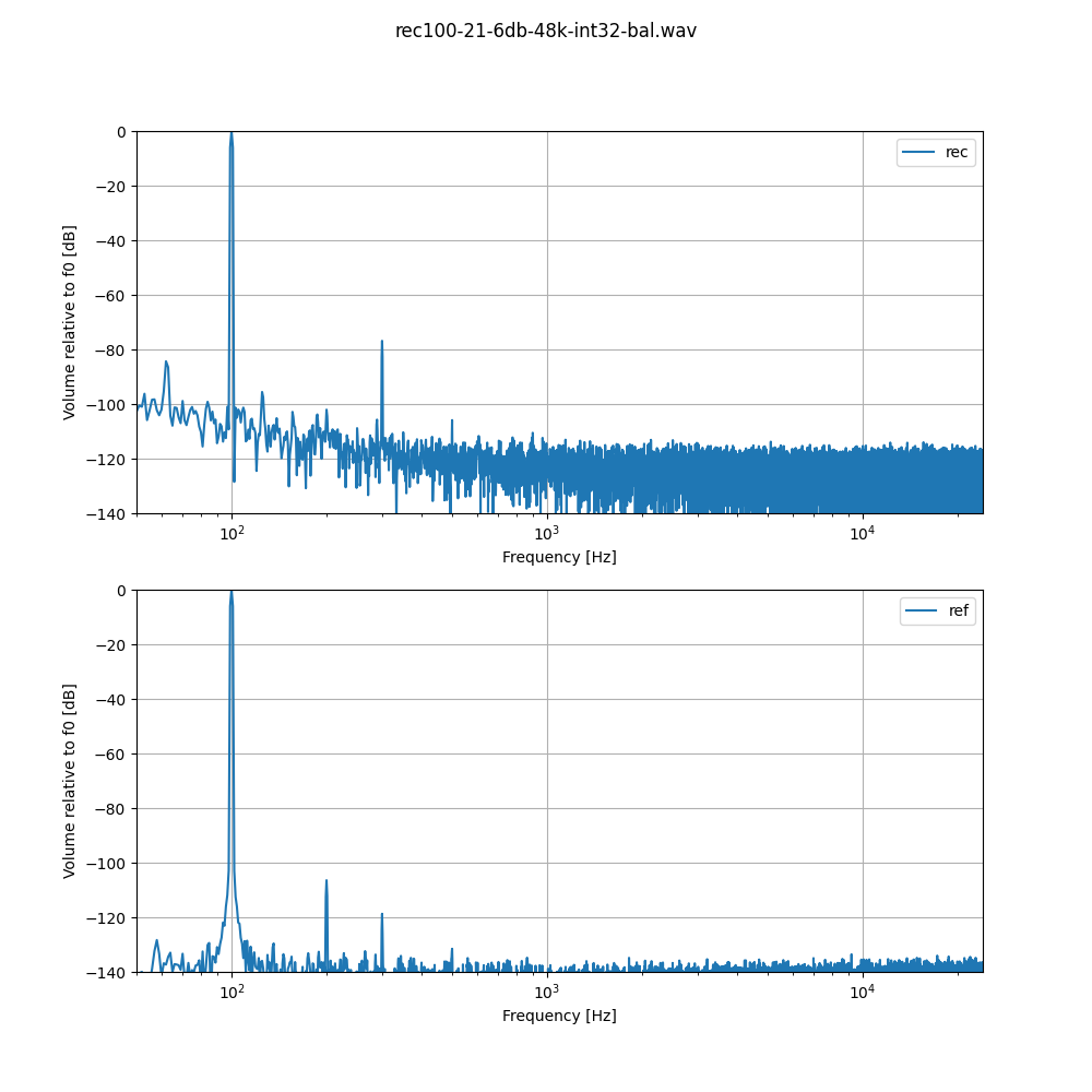
The fact that the output signal needs to be pretty low for a good THD is not a big problem for our application. The DSP will be attached to a power amplifier with 500W/channel, meaning that -20 dB is still equivalent to 50W, quite some volume.
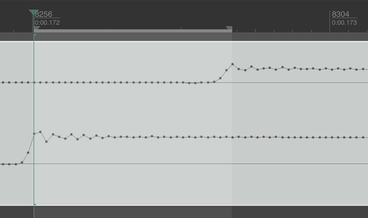
DSP Latency
The latency at 48 kHz sample rate was measured by using a sawtooth waveform at 1 Hz and comparing the two channels, one routed through the DSP, one directly looped back to the audio interface. The total DSP IO latency amounts to 32 samples, or 0.67 ms.
Crossover design
This is the design for a crossover with 6 balanced inputs and 6 balanced outputs.
If the xover on switch (or GPIO) is off, the 6 inputs are routed directly to the outputs, with volume attenuation.
If the switch is on, input channels 1 (left) and 4 (right) go through two Linkwitz-Riley crossovers, LF routed to output channel 1 (left) and 3 (right) through a delay line, and HF to output channel 2 (left) and 4 (right). Input channels 3 and 6 remain directly routed.
Volume is taken either from the internal slider or from AUX ADC channel 1, and converted to Decibel scale (-100 to 0). All channels are attenuated by the same factor.
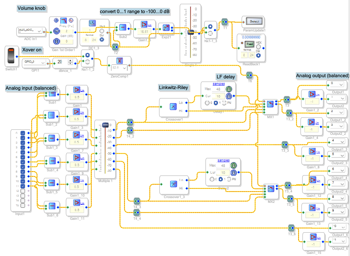
Still missing is EQing and limiters for all channels.